
BESS Explosion Protection Solutions
TKC × RSBP — Two-Stage Protection · Directional Venting · Full Verification
For containerized BESS thermal runaway explosion risks, TKC and RSBP provide a two-stage protection system: BESS Vent active venting (Stage 1) + Vent PRO F explosion relief panel (Stage 2), with optional DivEx directional venting to reduce internal peak pressure from 7–8 bar to 0.1–0.2 bar.
Thermal Runaway Creates Explosive Gas Environments
The destructive event is not just battery fire, but the deflagration that occurs after gas accumulates inside the container. LFP chemistry reduces fire risk but cannot eliminate thermal runaway gas generation.
Cell failure → severe fault triggers gas generation and heat release
Gas accumulation → combustible gas builds up inside the battery container
Ignition + pressure surge → deflagration generates destructive overpressure
Subsequent deflagration may cause container rupture, secondary flame spread, downtime, and personnel exposure
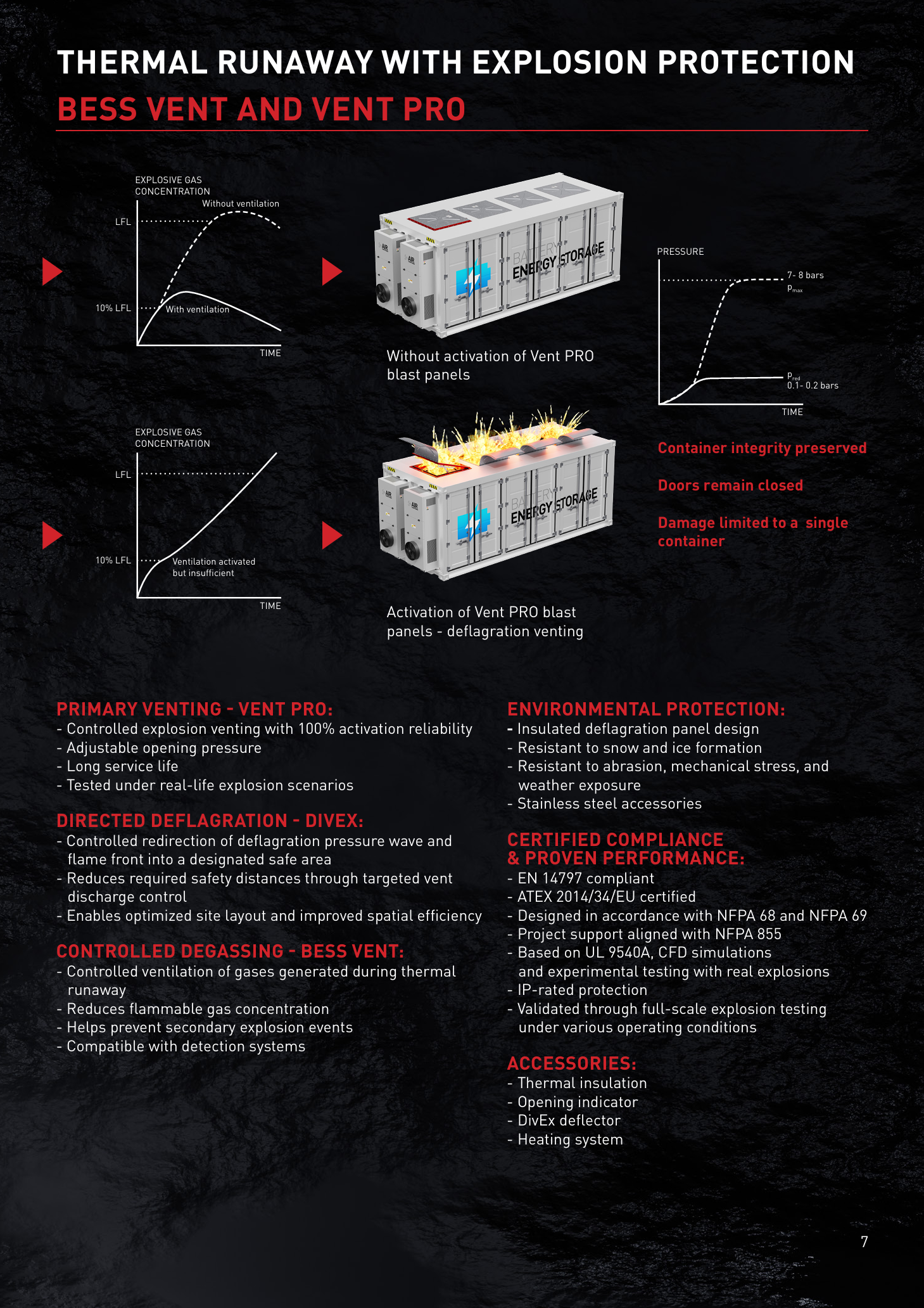
Unprotected internal peak pressure
Controlled relief pressure after venting
First active venting, escalation triggers relief
Vent PRO activation reliability under test conditions
Differentiated Response to Early Gas Generation and Escalating Thermal Runaway
The system responds differently to early gas generation and escalating thermal runaway events, ensuring the most appropriate protection at each stage.
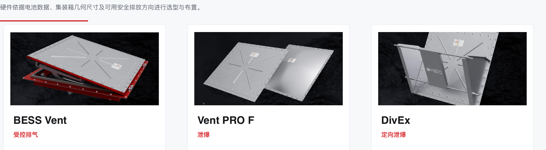
Stage 1 | Controlled Venting
BESS Vent Active Venting Unit
Opens via linear actuator to reduce explosive gas concentration before ignition conditions form. Ideal for scenarios with early gas detection where the design goal is pre-ignition concentration reduction.
| Static Opening Pressure | 10 kPa ±15% |
| Protection Rating | IP66 |
| Snow/Wind Load | 1 m fresh snow / 185 km/h |
| ATEX Classification | II G/D · Cat.1/Cat.3 |
| Actuator | 3000 N · 12–24 VDC |
| Full Open Time | 25–50 s · 20–30° |
| Operating Temp | −25 °C to +65 °C |
Stage 2 | Explosion Relief
Vent PRO F Explosion Relief Panel
When gas accumulation cannot be controlled, Vent PRO F reliably opens to release pressure from the protected enclosure. Reduces unprotected peak pressure pmax (7–8 bar) to controlled relief pressure pred (0.1–0.2 bar).
| Standard Size | 1000×1000 mm |
| Insulated Size | 1020×1020 mm |
| Static Activation Pressure | 10 kPa ±15% |
| Vent Area (Standard) | 0.99 m² |
| Vent Area (Insulated) | 1.03 m² |
| Material | AISI 304 / EPDM |
| Temp / Vacuum | 100 °C / −0.05 bar |
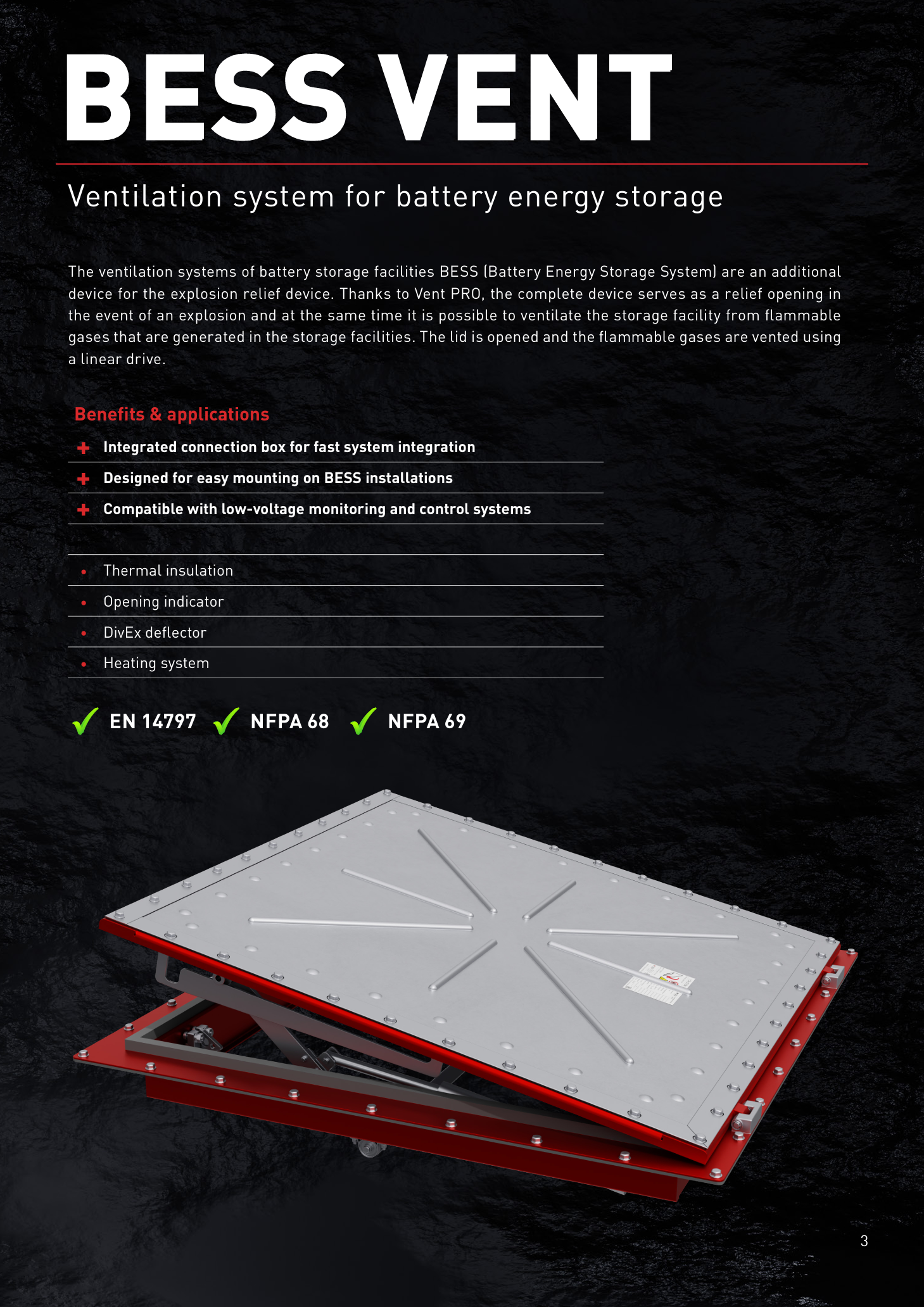
BESS Vent — Active Venting Unit (Stage 1)
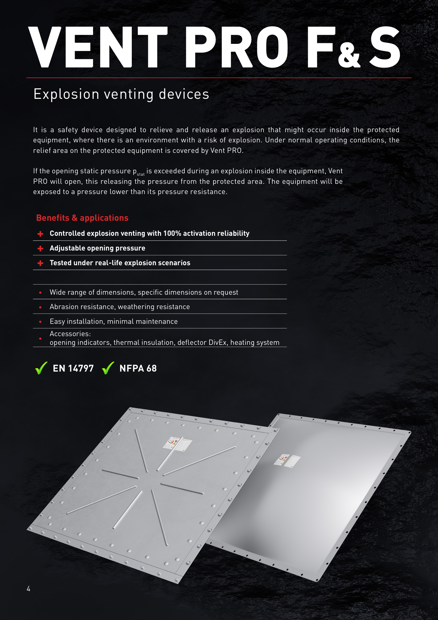
Vent PRO F — Explosion Venting Panel (Stage 2)
Optional Add-on
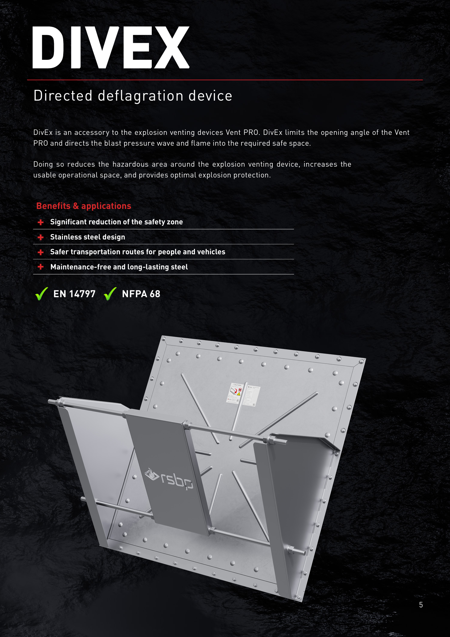
DivEx Directional Venting Deflector
For dense site layouts, DivEx redirects pressure waves and flame fronts to designated safe venting paths, reducing hazardous exclusion zones and protecting adjacent BESS units, structures, personnel access routes, and vehicle traffic areas. DivEx should only be used when confirmed that venting discharge can avoid personnel, structures, and adjacent BESS units.
| Pred.max Range | 0.6–1.2 bar (model dependent) |
| Venting Efficiency | 65–80% (model dependent) |
| Opening Angle | 50° |
| Compatible Panel Size | 1020×1020 mm |
| Certification | EN 14797:2006 & EN 14491:2012 |
Flexible Solutions Adapted to Container Formats
Choose top or side installation, with or without active venting and directional discharge. Selection and layout are based on battery data, container geometry, and available safe venting directions.
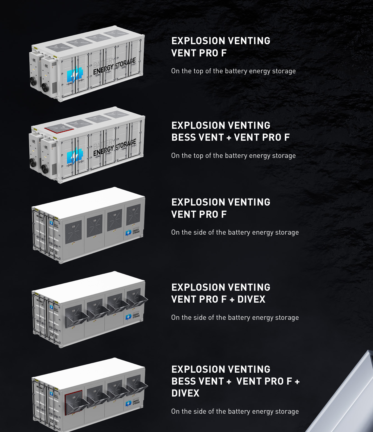
Top-Mount Primary Venting
Vent PRO F top-mounted, for standard configurations with clear overhead space.
Top-Mount Venting + Relief
BESS Vent + Vent PRO F top-mounted, combining active venting and passive explosion relief.
Side-Mount Primary Venting
Vent PRO F side-mounted, for layouts with overhead constraints.
Side-Mount + Directional Venting
Vent PRO F + DivEx side-mounted, redirecting pressure wave and flame front to designated safe zones.
Side-Mount Full Protection
BESS Vent + Vent PRO F + DivEx side-mounted, the highest protection level for dense site layouts.
Selection criteria: clear venting path · battery gas data · target pred · safety zone constraints · AHJ/insurance requirements
Complete Workflow from Test Data to Safety Justification
Design is confirmed through battery data, CFD modeling, NFPA 68 sizing calculations, and (when necessary) full-scale battery test data.
Battery Test Data
UL 9540A cell/module/unit data: gas composition, LFL, Pmax, burning velocity, and heat release.
CFD Simulation
Simulate gas dispersion, pressure rise, flame propagation, and venting effectiveness.
NFPA 68 Sizing Calculation
Calculate required vent area Av, target pred, and vent opening locations.
NFPA 69 Review
Verify combustible gas levels relative to LEL, determine if prevention systems are required.
Full-Scale Verification
Confirm pressure wave remains within safe limits via test data or project testing. Deliverables: vent area calculations, CFD summary, configuration drawings, product datasheets, certification basis, and installation instructions.
Complete BESS Safety Product Range
From controlled venting to enclosure systems, TKC offers products covering all BESS safety scenarios.
BESS Pressure Relief Panel (ATEX Certified)
ATEX certified, specifically designed for BESS thermal runaway explosion scenarios. VENT PRO S series reliable venting panels for effective BESS protection.
Fire-Resistant & Venting Container Houses
Modular container houses for hazardous-material storage and personnel refuge. DLC models may be configured with a TKC venting wall project by project; the complete unit structure and venting solution are defined by project technical documentation.
European Hardware Certification + US Design Methodology
The product range simultaneously satisfies EN/ATEX requirements and NFPA-based project engineering, covering China, Europe, and North American markets.
Explosion Venting Devices — Testing, marking, conditions and performance
EU Type Examination KDB 23ATEX0018X (Notified Body NB 1453)
Explosion Protection by Deflagration Venting — calculation and layout
Explosion Prevention Systems — combustible gas concentration control
Installation of Stationary Energy Storage Systems — safety basis and AHJ support
Test Method for Evaluating Thermal Runaway Fire Propagation in BESS
Note: Final applicable versions and AHJ acceptance criteria must be confirmed based on the project's jurisdiction and permitting pathway.


TKC's BESS Safety Expertise
FM 4440 venting-system manufacturing capability — confirm applicable scope against the relevant certified product and technical documentation
RSBP Authorized Partner — Czech European-certified hardware + localized delivery and after-sales coordination
NFPA 68-based precise venting area calculation, with CFD simulation and full-scale verification
Solution, supply, and engineering coordination organized around project-specific design, installation, and documentation delivery
Design calculations, product documentation, and project records to support technical review by insurers and owners
Required Client Input Data
Container geometry — internal volume, vent opening location, wall/roof construction
Site constraints — adjacent containers, structures, access routes, safe venting directions, exclusion zones
Battery information — cell chemistry, rack layout, capacity, module arrangement, and UL 9540A gas data
Environmental loads — outdoor temperature, snow, ice, corrosion class, and protection rating requirements
Explosion parameters — LFL/UFL, Pmax, KG or burning velocity, gas generation rate, and target pred
Approval pathway — AHJ, insurance, and regional standard requirements
Upon receipt of the above information, TKC and RSBP can proceed to prepare NFPA 68 sizing basis, configuration recommendations, CFD scope, and commercial proposal.
Consult BESS Explosion Protection Solutions
TKC's expert team will provide customized safety solutions based on your BESS scale, battery type, and site conditions.